Getting Started
This guide walks you through building a simple scatter tool from scratch: a node graph that places copies of a mesh across a surface, with an exposed density slider a designer can tune in the scene.
No C# required. You’ll work entirely in the graph editor.
Before you start
Make sure you’ve installed Infinio.
You’ll need:
- A mesh to scatter (a rock, a bush, anything small). If you don’t have one, you can generate a primitive to grey-box the idea.
- A surface mesh to scatter onto (a plane, a terrain mesh, anything flat-ish). Again, if you don’t have one, you can generate it.
Both need to be Mesh assets. If yours are inside an .fbx, expand the model in the Project window and use the Mesh you find nested under it - the model root itself is a GameObject and Infinio will not take it.
Step 1 - Create a graph asset
In the Project window, right-click inside any folder and choose Create → Infinio Graph. A template picker opens. Choose Blank and name the asset something like MyScatterTool.

Double-click the asset to open it in the graph editor. The canvas is empty - Blank means blank. To the left is the sidebar (Parameters, Tool); to the right is the preview pane.
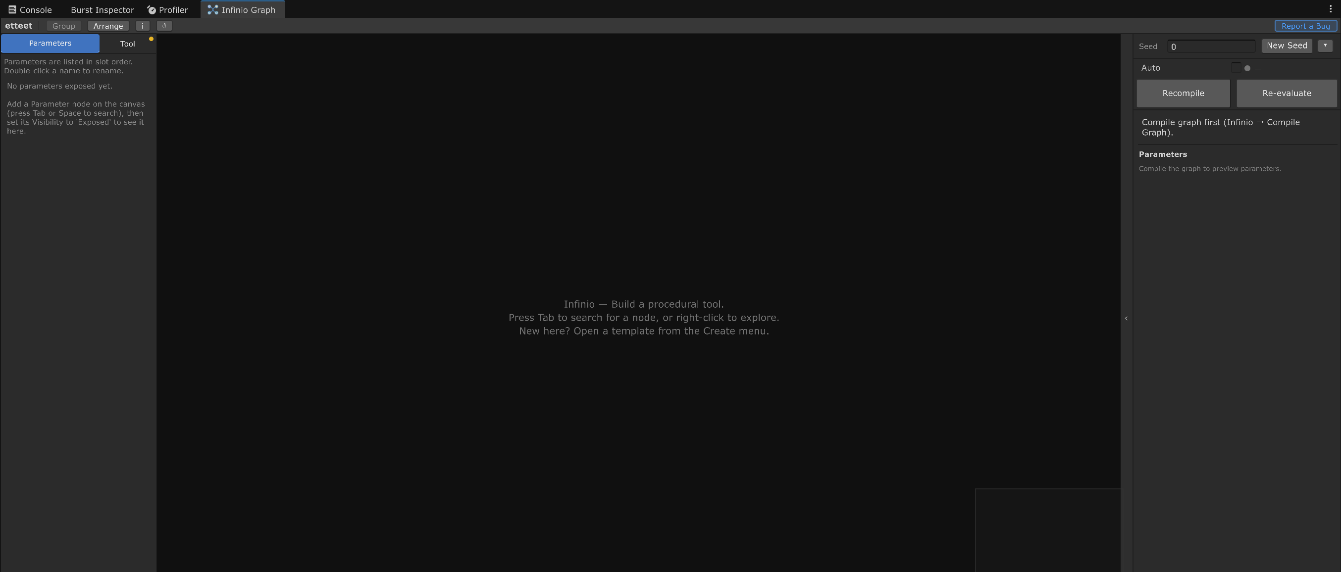
To add a node, right-click empty canvas and choose Create Node, or just press Space. Either way you get a search field - type part of a node’s name and press Enter. We’ll add a node in the next step.
Every node carries an (i) button in its title bar: click it for that node’s own documentation. It is also on the node’s right-click menu as Documentation.
Step 2 - Add a surface
Every scatter needs something to scatter onto. Add a Mesh Asset node (search for Mesh Asset), then drag your surface mesh from the Project window straight onto the node’s body. It snaps into the node’s Mesh slot. Drag the Mesh itself, not the model root. If nothing snaps in, expand the .fbx in the Project window and drag the Mesh nested under it.
If you don’t have a mesh asset to use right now, create a Plane geometry node. Set Width and Depth to 20 so it generates a 20-unit plane (search for Plane).
You should see a small preview thumbnail appear on the node - that’s the geometry preview, live-updating as you build.

Geometry travels along the red wires. The thumbnail on the node and the large preview on the right both update as you edit.
Step 3 - Scatter points onto the surface
Add a Surface Scatter node (search for Surface Scatter).
Connect the Geometry output of the first node to the Geometry input of Surface Scatter. This data type is coloured red throughout the graph editor.
Set Count to something like 200. Count is an absolute number of points, not a density - you’ll add the density control in Step 5.
Surface Scatter emits Spawns: positions and orientations, already aligned to the surface normals. Spawns are not geometry yet, so this output does not connect to Geometry Output directly. Spawn data is coloured cyan throughout the graph editor.
Step 4 - Place a mesh at every point
Add a second Mesh Asset node and drag your instance mesh onto it. Then add an Instancer node (search for Instancer).
If you don’t have an instance mesh handy, create a primitive by searching for Primitive in the node search and picking one, such as Box. Then add the Instancer as above.
Connect:
- The Geometry output of the second mesh node → the Geometry input of Instancer (this is the template that gets copied)
- The Spawns output of Surface Scatter → the Spawns input of Instancer
Finally, add a Geometry Output node and connect Instancer’s Geometry output to its Geometry input. Geometry Output is the terminal node - it is what the tool actually renders.
The preview now shows your instance mesh copied across the surface.
Step 5 - Expose the density as a parameter
Add a Density Mask node (search for Density Mask) and slot it between the scatter and the instancer:
- Surface Scatter Spawns → Density Mask Spawns
- Density Mask Spawns → Instancer Spawns
Density Mask thins the spawn list. Its Density input runs 0 to 1 - keep none, keep all - and the thinning is spatially stable, so the same point makes the same keep/discard decision every evaluation.
Now make that value tunable. Add a Float parameter node (search for Float - it’s under Parameter, with an ‘input’ tag next to it in the search list) and connect its Value output to Density Mask’s Density input. Set the node’s Default field to 0.5. A new Float parameter starts at 0, which would blank the preview the moment it is wired in, so set the Default before you connect it, not after.

Open the Parameters tab in the left sidebar (it’s probably already open). Your parameter is listed there - double-click its name and rename it to Density. You’ll also see three dropdowns: Visibility (already Exposed, which is what makes it show up in the designer’s inspector - leave it), a scene-handle type (leave it None for this tutorial), and a section group label (leave it blank). The defaults are fine here; none of the three needs changing to finish this guide.
Tick the Min and Max checkboxes, then set them to 0 and 1. The value fields are greyed out and already read 0 and 1 until you tick their boxes, and both boxes must be ticked before the designer’s inspector shows a slider instead of a plain number box.

Step 6 - Place it in a scene
While you’re working, your graph will have been saving automatically.
Drag the graph asset out of the Project window and drop it onto the Hierarchy, then select the new object and press F to frame it. Infinio creates a GameObject for you, adds the InfinioInstance component, wires in the compiled result, assigns a default lit material, and evaluates immediately.
Name the tool on the Tool tab in the left sidebar. That is also what clears the amber “Name this tool” chip you’ll see on the graph while it is unnamed - the shipped examples show the same chip until they’re named too.
In the Inspector you’ll see the Density parameter you exposed - drag the slider and watch the scatter thin out and fill back in.
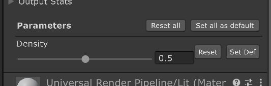
Note that the Inspector’s Graph Asset slot holds the compiled result, not the graph you were editing. That is why dropping the graph into the scene is the route in, rather than adding the component by hand and hunting for the asset.
What just happened
You built a procedural tool:
- The graph is the authoring surface - you edit it in Infinio’s editor
- The
InfinioInstancecomponent is the runtime tool - a designer uses this component without ever opening the graph - The
Densityparameter bridges the two: authored in the graph, tuned in the scene
The graph compiles to a self-contained binary. Changing a parameter value in the inspector does not re-run the graph compiler - it re-evaluates the compiled binary, which is fast.
Next steps
- Add a Transform node between the instance Mesh Asset and the Instancer, then drive its Scale X/Y/Z from a Float parameter to make instance size tunable
- Add a Random Scale per Point or Random Rotation per Point node after Density Mask so every copy varies
- Add a Slope Filter after the scatter to keep instances off the steep parts of your surface. It has no visible effect on the flat Plane from Step 2: try it on a terrain mesh to see it work.
- Explore the example graphs included in the package - each one is an editable Infinio graph you can pull apart
Stuck? The Scatter Base template (in the template picker from Step 1, Create → Infinio Graph) is the same graph shape, already wired, with the surface merged into the output - not the answer sheet, since it has no Density Mask, but a useful reference. Otherwise head to Discord - describe what you were trying and where it stopped making sense.